
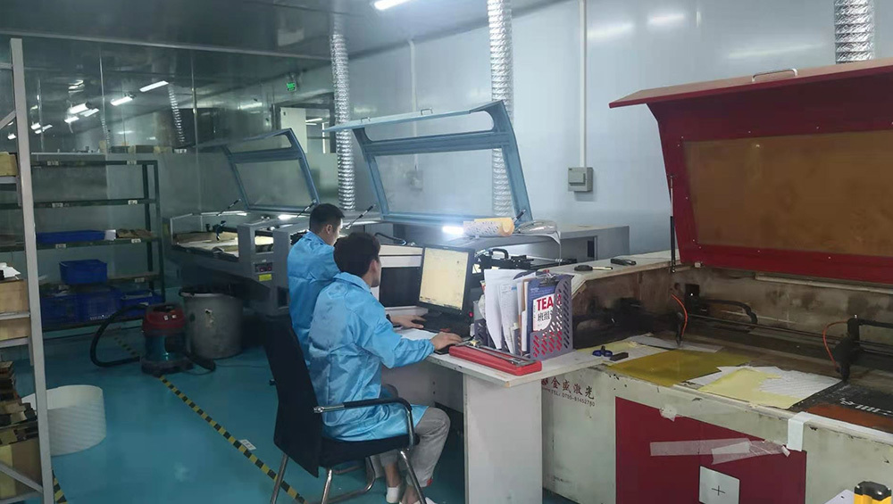
Engineering review and prototyping
Review dimensions, artwork, circuit matrix, tail exit, connector, enclosure surface, adhesive boundary, operating environment, and approval criteria before tooling.
Review engineering supportJASPER connects engineering review, printed electronics, layer conversion, assembly, inspection, and export packing in one released build specification for custom interface projects.
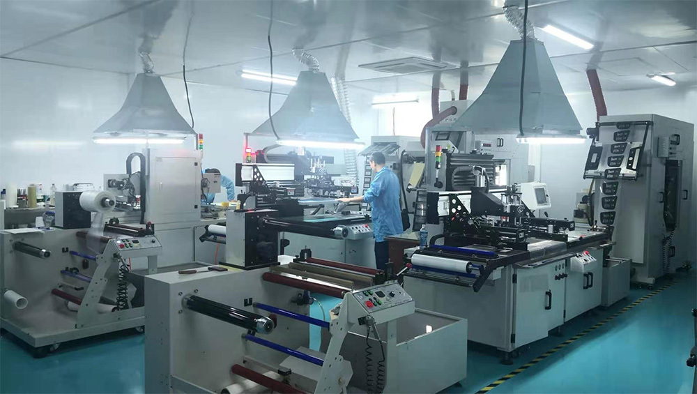
A membrane switch is not only a printed face or a circuit layer. The overlay, spacer, adhesive, domes, tail, connector, backer, enclosure, and inspection criteria have to work as one construction. JASPER reviews those interfaces before samples are released and carries approved decisions into production instructions.
The factory introduction shows the working environment, production equipment, printing, handling, and assembly behind JASPER interface products.
The route is selected from the complete part construction. A simple printed overlay, a tactile membrane switch, and a ready-to-install HMI assembly do not need the same tooling or inspection plan.
Review dimensions, artwork, circuit matrix, tail exit, connector, enclosure surface, adhesive boundary, operating environment, and approval criteria before tooling.
Review engineering support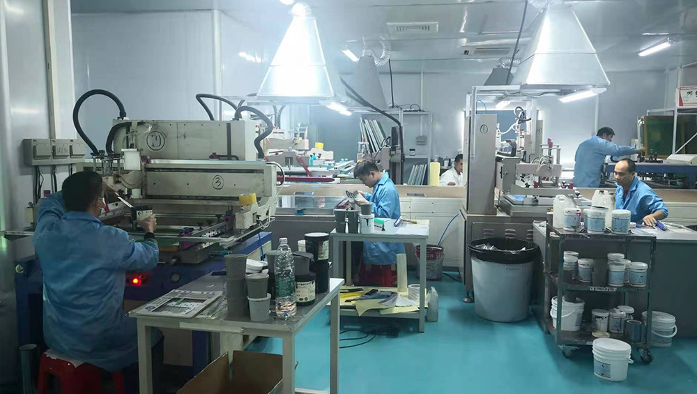
Prepare films, colors, opaque layers, windows, legends, conductive silver circuits, and carbon contact areas to the released artwork and circuit requirement.
Review membrane switch work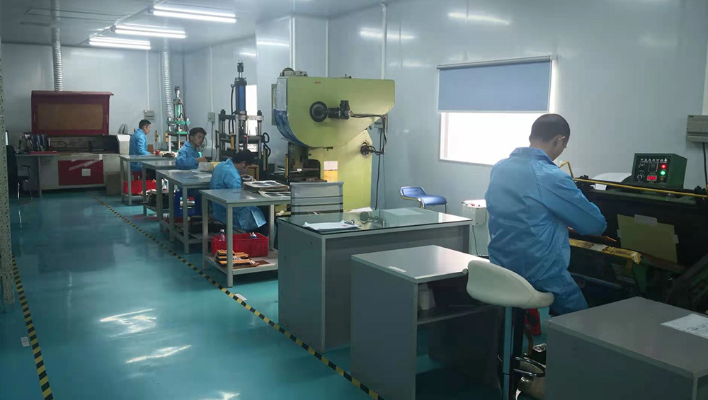
Convert overlays, spacers, adhesives, circuits, gaskets, and support layers while controlling openings, registration features, outer edges, and tail geometry.
Review overlay conversion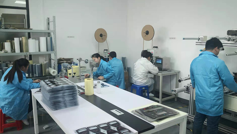
Align the layer stack, place domes and LEDs, laminate adhesives, route tails, install connectors or backers, and protect cosmetic surfaces during assembly.
Review HMI assemblyThe same factory workflow can support an early engineering sample, an approved pilot build, or a repeat order, but each stage needs a different release boundary.
Use drawings, marked photos, enclosure data, or an existing sample to define the first build and identify unanswered interface decisions.
Confirm artwork, color, fit, key response, backlighting, connector, adhesive, and inspection criteria before repeat production is released.
Build to the approved revision, apply agreed inspection points, control labels and packing, and route proposed changes back through review.
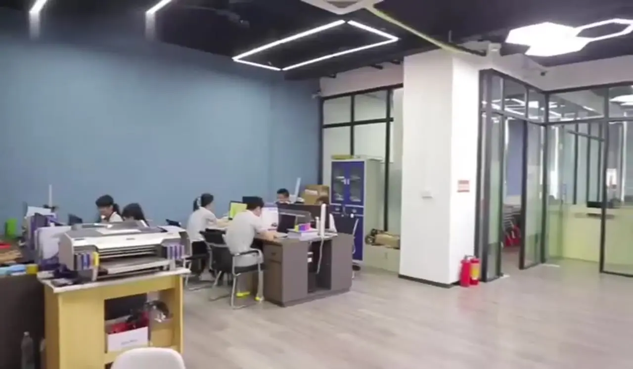
Most avoidable failures happen between disciplines: artwork does not match the enclosure, a tail cannot reach the connector, an adhesive does not suit the housing, or inspection criteria arrive after sampling. JASPER coordinates those boundaries as one project rather than as isolated machine operations.
A generic claim of quality is not an inspection plan. The useful control points are the ones connected to the part: visible finish, dimensions, registration, continuity, key response, tail orientation, connector details, labels, and packing. Project-specific records should be agreed during quotation and sample approval.
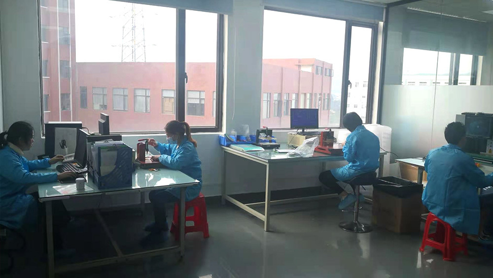
Use these focused pages to review what is controlled, which project inputs are required, and what evidence closes each manufacturing step.
Review JASPER precision die cutting for overlays, circuits, spacers, adhesives, gaskets, windows, tails, liners, and custom HMI layer conversion.
Review JASPER lamination and assembly for membrane switches, graphic overlays, adhesives, domes, LEDs, tails, connectors, backers, PCBs, displays, and HMI fronts.
The six stages below follow the purchasing and engineering decisions that matter. Exact tools and inspection points are confirmed from the part construction rather than assumed from a catalogue name.
Send drawings, artwork, circuit or pinout, connector data, enclosure information, operating conditions, quantities, and required records.
Engineering identifies open decisions, proposes the layer and assembly route, and aligns quotation assumptions with the requested deliverables.
Films, cutting data, fixtures, materials, circuits, and components are prepared for the agreed prototype or sample build.
Fit, graphics, color, tactile response, lighting, electrical behavior, connector, adhesive, and inspection references are reviewed.
Printing, conversion, lamination, assembly, and handling follow the released revision with checks at agreed control points.
Finished parts are checked for the agreed visual, dimensional, functional, labeling, quantity, and packing requirements before shipment.
These pages explain the construction choices inside each product family. The final manufacturing route still depends on the drawing, enclosure, electronics, environment, and approval plan.
Tactile, non-tactile, waterproof, backlit, LED, metal-dome, PCB, and FPC constructions.
Printed legends, windows, dead-front graphics, textures, embossing, adhesives, and converted outlines.
Custom key geometry, legends, coatings, carbon contacts, light transmission, and interface fit.
Pressure and membrane sensing mats shaped around cushion geometry, cable routing, and connector requirements.
Printed or integrated touch interfaces reviewed with cover graphics, electronics, windows, and enclosure boundaries.
Interface layers, keypads, displays, PCB support, cables, backlighting, backers, and front-panel integration.
Custom printed medical and wellness electrode circuits where the conductive pattern, substrate, lead, and die-cut shape are project-defined.
The normal scope can include engineering review, film and artwork preparation, screen printing, printed circuit production, die cutting, layer conversion, lamination, dome or LED placement, connector and backer assembly, visual inspection, electrical testing, labeling, and export packing. The confirmed scope is listed in the quotation and released drawing package.
Yes. Prototype and pilot builds are used to resolve fit, appearance, key feel, lighting, connector, adhesive, and electrical questions. Repeat production should begin only after those decisions are captured in approved artwork, drawings, sample references, inspection points, and production instructions.
Send the 2D or 3D drawing, artwork, layer or construction notes, circuit matrix or pinout, connector requirement, enclosure material and surface, operating environment, sample quantity, annual demand, target schedule, and any required compliance or inspection documents. Mark any item that is still open.
Checks are selected from the approved part requirements. They can include material verification, print appearance and registration, dimensions, cosmetic criteria, circuit continuity, key response, LED operation, tail and connector details, labels, quantities, and packing. Required reports or sample-retention rules should be agreed before production.
JASPER reports that it has supplied solutions to customers in more than 30 countries. For each project, shipment terms, export labels, packing protection, document needs, delivery address, and buyer communication should be confirmed during quotation.
Send the drawing and project boundary. JASPER engineering can review the layer stack, artwork, circuit, connector, enclosure, inspection points, sample plan, and production handoff before quotation assumptions become tooling decisions.
Share the project basics. JASPER will review the stack, materials, connector, quantity, and production risks.